Technical Report

Phase & Polarization
Imaging Technology

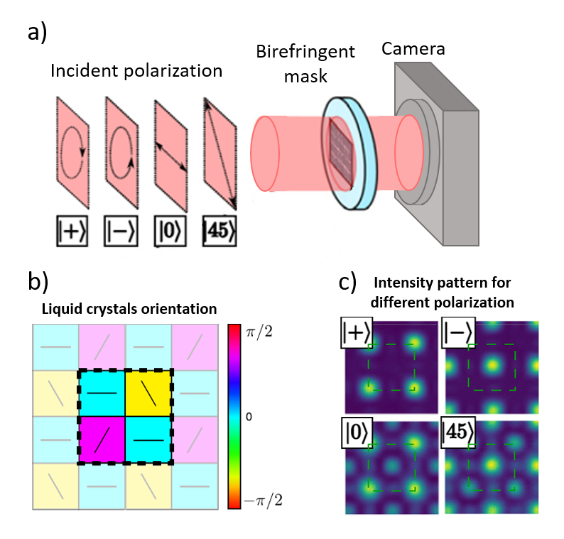
A detailed account of OPIRIS's birefringent diffractive mask architecture, enabling simultaneous capture of both the scalar and vector parameters of the light wave in a single acquisition.

The innovation lies in moving beyond conventional imaging (purely densitometric) by integrating a birefringent diffractive mask. Unlike standard cameras that only measure intensity, the OPIRIS system simultaneously accesses phase (φ) and polarization: the full vector state of the light wave, without any moving parts or external reference arm.
Birefringent diffractive mask and interferogram
Birefringent diffractive mask and resulting interferogram on the sensor plane
Part 1 · Physical Principles & Specifications
01

Physical and Optical Principles

Unlike standard cameras that measure only intensity (I), the OPIRIS system accesses both phase (φ) and the full polarization state of the wave vector simultaneously.

The Diffractive Mask: A two-dimensional liquid crystal grating. Each cell possesses a specific birefringence axis and retardance value, encoded by the orientation of the liquid crystal "rods."
Lateral Shift Interferometry: The mask splits the incident beam into 9 spatially shifted replicas that self-interfere on the sensor plane.
Self-Referencing: There is no external reference arm. The beam interferes with itself, making the system inherently robust against mechanical vibrations and environmental fluctuations.
Polarization Signature: The polarization state (right/left circular, linear at ) is encoded in the position and intensity of the interference pattern. A transition from circular + to circular results in a half-period shift of the dot pattern on the sensor.
02

Material Specifications and Fabrication

The mask is fabricated from liquid crystals oriented between two glass plates via photo-alignment layers, using technology analogous to modern LCD screens.

Component
Liquid crystals oriented between two glass plates via photo-alignment layers
Temporal Stability
Zero temporal drift. Photopolymerization possible for permanent fixation of orientation
Phase + Polarization mode
Absorbance near zero — the mask is fully passive and transparent. No flux loss
Polarization-only mode
50% of flux sacrificed due to the addition of an analytical polarizer (fundamental optical constraint)
03

Signal Processing and Resolution

The technology employs spatial frequency domain multiplexing. To reconstruct the full 4-dimensional polarization space, physical sensor pixels are grouped into macropixels, trading raw spatial resolution for quantitative information at every point.

Macropixel configurations
2×2, 3×3, 4×4, up to 6×6 pixels per interference pattern
Resolution trade-off
Raw spatial definition is traded for quantitative polarimetric and phase information at every macropixel
Calibration
A factory calibration phase determines the mask response matrix, enabling conversion of raw interference patterns into polarization and phase maps
Transformation Matrix: An initial factory calibration determines the mask response matrix, allowing direct conversion of raw interference patterns into quantitative polarization and phase maps with no iterative reconstruction.
Multiplexed macropixel configurations
Spatial frequency multiplexing: macropixel configurations encoding the full polarimetric and phase information
04

Optical Integration and Form Factor

Form factor reduction is the central challenge of the current development phase.

Current Prototype
The mask is placed in a Fourier plane, requiring a re-imager system (additional lenses) between mask and camera. This results in a module length of approximately 50 cm.
Industrial Target
Direct integration at < 1 mm from the silicon sensor, requiring removal of the sensor's protective glass and direct bonding of the birefringent mask. This high-precision de-capping stage is currently undergoing industrial transfer.
Experimental setup — view 1
Current prototype — experimental setup (1)
Experimental setup — view 2
Current prototype — experimental setup (2)
05

Comparative Analysis and Competitive Advantages

Compared to existing polarimetric and phase imaging approaches, the OPIRIS mask architecture offers a unique combination of single-shot acquisition, no moving parts, and compatibility with standard sensor platforms.

Capability Standard Camera Rotating-element Polarimeter OPIRIS Mask
Intensity IYesYesYes
Full Stokes polarizationNoYesYes
Phase φNoNoYes
Single-shot acquisitionYesNoYes
No moving partsYesNoYes
Vibration-robustYesNoYes
Drop-in sensor integrationYesPartialYes
Flux efficiency100%50%~100% (Phase+Pol)
06

Defense and Industrial Use Cases

Target Detection (Thales POC): Operated at 830 nm or 1550 nm, compatible with InGaAs and CMOS sensors. Polarization enables discrimination of painted metal plates (which maintain polarization) from rough or natural environments (which depolarize light), even under camouflage paint.
Photoelasticity: Quantitative analysis of mechanical stress in transparent materials (glass, polymers) by measuring the induced birefringence field at every pixel.
Plenoptic Imaging: Ability to extract depth information through phase measurement, enabling 3D reconstruction from a single 2D sensor frame.
Part 2 · Technical Deep Dive
D1

Mask Microstructure — The "Rods"

The mask is a two-dimensional grating, not merely a spectral filter. Its spatial encoding of polarization state is what enables single-shot full Stokes acquisition.

Birefringence Axis: Each zone contains oriented liquid crystals ("rods"). Their orientation angle defines the local birefringence axis, determining how that zone modifies the incoming polarization state.
Retardance: Colors in OPIRIS schematics represent retardance values (the magnitude of birefringence), not optical color. Retardance governs the phase shift introduced between the ordinary and extraordinary ray components.
4D Polarization Space: Using 4 calibration standards — signatures for circular +, circular , linear , and linear 45° — the mask covers the entire Poincaré sphere of possible polarization states.
D2

Interference Mechanism — Semi-Interferometry

Unlike Mach-Zehnder or Michelson interferometers that require a separate reference arm, OPIRIS implements semi-interferometry: the beam interferes with its own spatially shifted replica through the mask.

No External Reference
Both the original and shifted beams traverse the exact same optical path through the mask. Phase noise and vibrations affect both identically, cancelling out in the interference pattern.
Intrinsic Stability
Because common-path interferometry is used, the system is effectively blind to vibrations, making it viable for deployment on moving platforms including drones and airborne systems.
D3

Loss Management — The 50% Trade-off

Depending on the operating mode, the system handles the photon budget in fundamentally different ways.

Polarization Only
Requires an analytical polarizer. 50% of photons are discarded — a fundamental optical constraint. System absorbance is 50%.
Phase + Polarization
The mask is passive and transparent. Theoretically recovers ~100% of flux. The cost is shifted from light intensity to spatial resolution: more pixels are required to decode the data per macropixel.
The Phase + Polarization mode is the preferred operating mode for photon-limited environments (long-range, passive illumination, SWIR night imaging), where preserving flux is critical.
D4

Biological Analogy — Insect Vision

Many insects use polarization to identify bodies of water. The surface of calm water produces a highly polarized reflection that is distinct from surrounding terrain, allowing navigation without visual landmarks.

The Car Hood Challenge: For a polarimetric sensor, a smooth car hood and a body of water appear nearly identical in polarization signature. Both produce strong, similarly polarized specular reflections. This presents a concrete segmentation challenge that algorithmic processing must address, and represents an active area of OPIRIS software development.
D5

Hardware Integration Constraints

Optical Spacer: Used to calibrate the distance between the mask and the sensor (when not directly bonded), ensuring the interference pattern aligns with the pixel grid at the correct spatial sampling rate.
De-capping: For the ultra-compact version, the protective glass of the CMOS or InGaAs sensor must be removed, often under vacuum or controlled atmosphere, to place the mask within < 1 mm. This is precision work performed on a camera.
The Re-imager: Reducing the current 50 cm prototype to 25 cm or less requires a complete redesign of the objective head optics. This is the primary engineering challenge for the next product generation.
D6

Sources and Wavelengths

The system is designed to operate across the SWIR band, with specific configurations for active and passive imaging scenarios.

Operating wavelengths
830 nm (CMOS-compatible), 1550 nm and 1640 nm (InGaAs SWIR)
Active illumination
Laser diodes up to 30 W for long-range active imaging at 20 m. Significant power for embedded systems; thermal management is a design constraint.
Passive imaging
In passive mode, the image can be divided by intensity to yield purely polarimetric contrast, effectively eliminating solar shadows and illumination non-uniformities from the scene.
Sensor compatibility
CMOS (silicon, up to ~1000 nm), InGaAs (900-1700 nm). The mask architecture is sensor-agnostic and can be bonded to any flat focal plane array.